Part Number
|
Callout
|
From
|
To
|
Description
|
Suggested Retail
|
1W7Z-2C335-AA
|
2C335
|
2001
|
2003
|
Traction Control On/Off Switch
|
$23.62
|
1W7Z-9G604-AA
|
9G604
|
2001
|
2003
|
Adjustable Pedal Control Switch
|
$12.32
|
XF1Z-9F924-AA
|
9F924
|
1998
|
2000
|
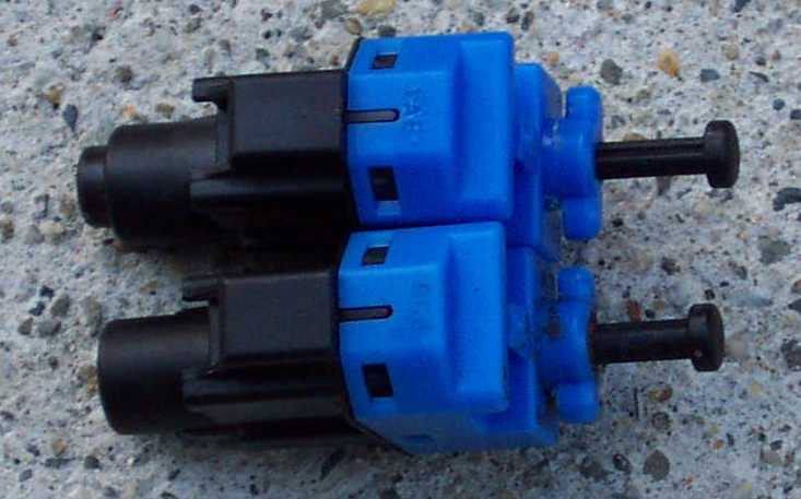
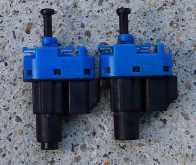
Speed Control Deac Switch
|
$5.29
|
1F1Z-9F924-AA
|
9F924
|
2001
|
2003
|
Speed Control Deac Switch
|
$23.91
|
F0AZ-13480-A
|
13480
|
1990
|
2000
|
Stoplight Switch Assembly
|
$14.73
|
YF1Z-13480-AA
|
13480
|
2001
|
2003
|
Stoplight Switch Assembly
|
$17.47
|
F0AZ-2B450-A
|
2B450
|
1990
|
2003
|
Brake Pedal Support Spacer (Plastic spacer in
between the brake pedal assembly housing and the firewall. Power brake
booster studs pass through this part.)
|
$6.57
|
C5DZ-2B129-B
|
2B129
|
1980
|
2003
|
Brake Master Cylinder Pushrod Spacer (Plastic
washer that goes over the rod on the brake pedal that the power brake
booster connects to)
|
$0.50
|
F1VY-9725-A
|
9725
|
1992
|
2000
|
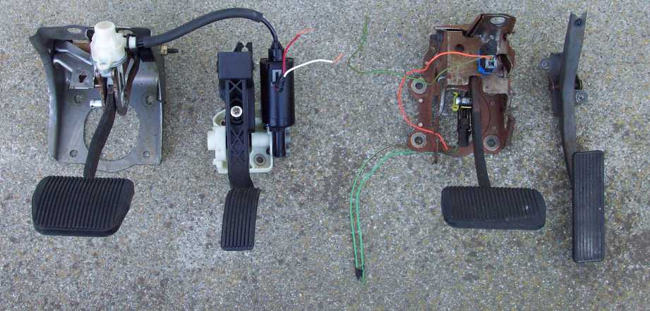
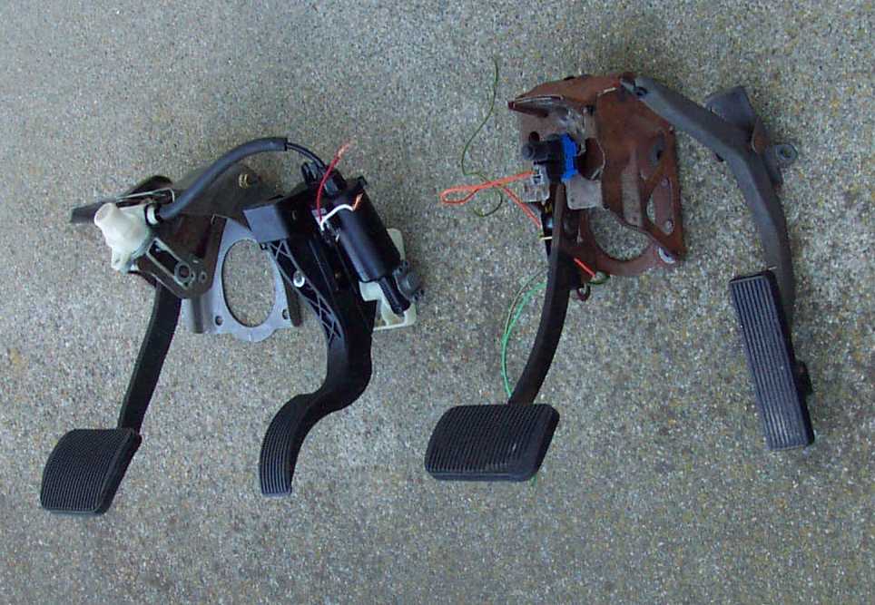
Accelerator Pedal Fixed
|
$66.06
|
1W1Z-9725-AA
|
9725
|
2000
|
2002
|
Accelerator Pedal Adjustable without Memory
|
$99.11
|
3W7Z-9725-BA
|
9725
|
2002
|
|
Accelerator Pedal Adjustable with Memory
|
$169.57
|
3W7Z-9725-AA
|
9725
|
2003
|
|
Accelerator Pedal Adjustable
|
$121.13
|
1W1Z-2455-BB
|
2455
|
2001
|
2002
|
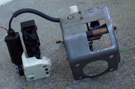
Brake Pedal Assembly (Motor and cable only
avaliable in accelerator pedal assembly)
|
$106.95
|
3W1Z-2455-BA
|
2455
|
2003
|
2003
|
Brake Pedal Assembly (Motor and cable only
avaliable in accelerator pedal assembly)
|
$106.95
|
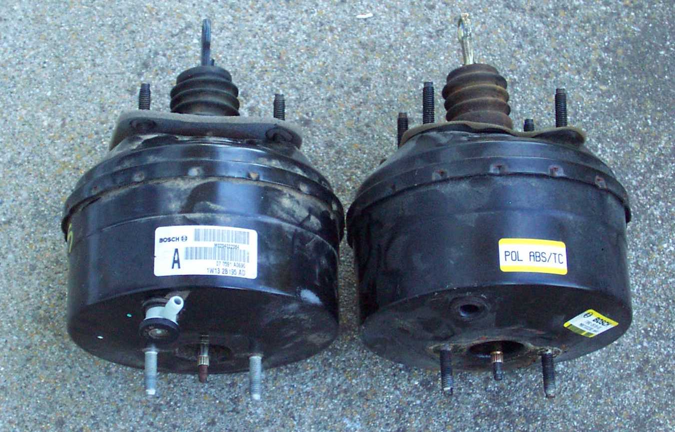
1W1Z-2005-AA
|
2005
|
2001
|
2002
|
Power Brake Booster Less Electronic Stability
Program (IVD) (use with #1W13-2B195-AC/BC or #1W73-2B195-CC)
|
$170.60
|
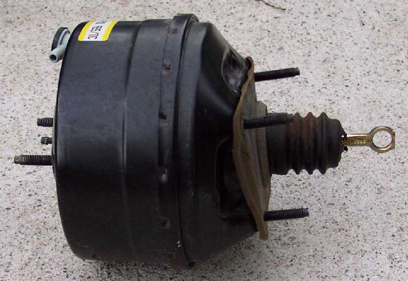
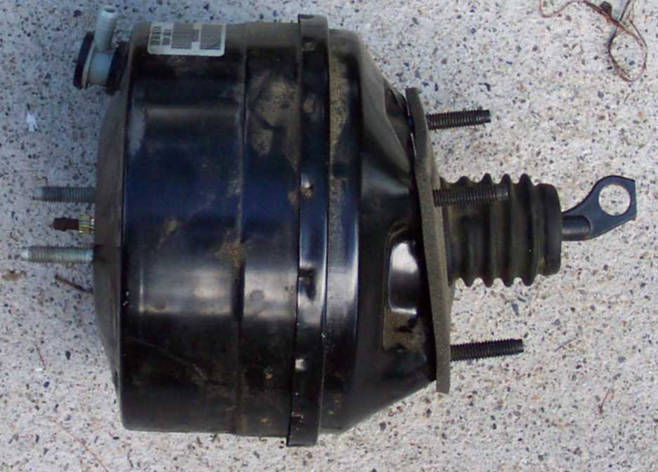
3W1Z-2005-AA
|
2005
|
2003
|
2003
|
Power Brake Booster Less Electronic Stability
Program (IVD)
|
$170.60
|